
I was thinking about building a delay circuit quickly and effectively and with small footprint. The idea is to delay a signal either from a camera or from other camera triggering devices and then trigger a flash after the delay.
Beside my need to build such a circuit, it is also my goal to share it and make it DIYable. Therefore, using a small microchip came up to my mind. One such MCU is Attiny45 series by Atmel (now Microchip) as it is so popular and you can use an Arduino to program it. While searching for Attiny45, I came across something that I have forgotten — DigiSpark boards!
DigiSpark board was made possible by DigiStump LLC, these folks are geniuses who crammed a USB bootloader into tiny Attiny85 chip and still have about 6K flash left for programmers, which for most applications, 6K is enough. It is also compatible with Arduino development environment which is a huge plus and it can be programmed via USB connection. It is an amazing little board.
Installation
First thing first, installation. Heading to installation guide, it is much easier to do. To start, you do need to download Arduino development environment as per installation instruction. One thing that is worth mentioning is part to install DigiStump development into the Arduino environment. This is the important part: copy and paste this
http://digistump.com/package_digistump_index.json
into Arduino environment under File->Preference like below.

The rest of installation is as easy as following instruction on the page.
Development in Arduino IDE
After installing DigiStump on Arduino IDE, it is time to develop and deploy but make sure you set the right Programmer and select the right board per installation instruction above.
Once you finished coding, unlike Arduino that you can plug it into your computer all the time, you can not do that. If you leave your DigiSpark plugged into your computer and try to upload your code to it, very likely you will encounter the following error:

So, leave your DigiSpark board unplugged, click Upload on Arduino IDE and wait for prompt to plug in the board. This is the part I had trouble with, so it is worth mentioning it here.
Beside above warning or tip, because DigiSpark is such small MCU, its pins are purposed to many other tasks, such ADC, digital, I2C pins, etc. If you encounter some weird upload error, unplug your DigiSpark board from your circuit and program it that way.
Impressions
The first thing that strikes me is DigiSpark’s friendly design for bread board prototyping. Notice the three pins for power, namely, 5V, GND, VIN. If you do not solder all three pins, but just two of them, like 5V and GND, or GND and VIN, you can plug your board into a bread board with power rails like these:
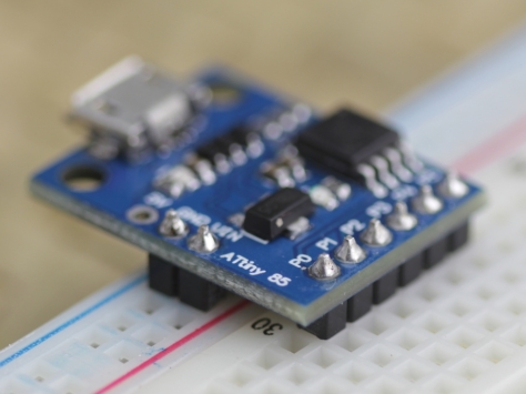
Notice the VIN and GND can fit very well into the power rail of a bread board while the actual pins are also inserted. This allows the board to be powered from the power rail and because it has voltage regulator, it will work and also power other components
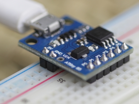
Here, the 5V and GND are inserted into power rail on the bread board while all other pins are inserted, too. This allows the circuit to be powered by a USB power bank for phones. This is my favorite configuration with one important warning: the 5V is now inserted into the blue line where normally it is marked as – sign and the GND is inserted into the red line where it is usually marked as + sign, so keep this in mind when wiring.
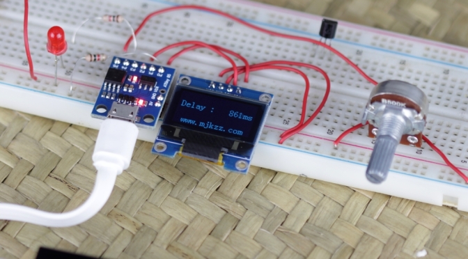
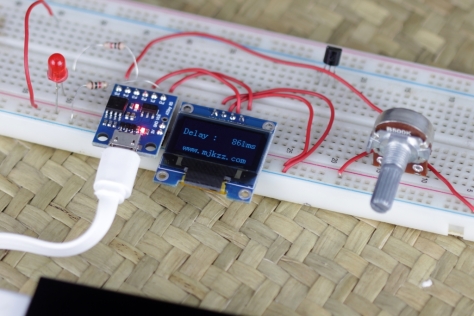
The second thing is plethora libraries for this tiny board. One such library is the OLED screen driver. On the same day I received my DigiSpark boards (probably a “bad” clone), my order of an 0.96″ OLED screen intended for other projects also arrived. Learning how to program the DigiSpark, I saw that there is this OLED library with sample, so I quickly wired it up (only four wires, 5V, GND, SDA, and SCK), initially, it did not work as my OLED has an I2C address of 0x78, I guess the default library is something else, so I defined address to be 0x78 (see attached code) and it worked right away. I was totally amazed by it.
One bad impression I got is that the pin 5 still has RESET enabled. This is probably due to the cheap clone I got (DigiStump has temporarily stopped shipping). This essentially renders the board to have one less (or half less, see more) pin and it is dangerous if this pin is left floating which will cause the board to reset randomly. The reason I say it is probably half pin is that it seems I can still use it as an analog pin, only when voltage drops below 2.5V (on 5V power), it resets. Above 2.5V, I still can read good reading from this pin.
Another thing that is different from Arduino is that when powering up, it takes about 5 seconds to get to your code. This is because the boot loader needs to determine if any new code are being loaded upon powering up.
Conclusion
Overall experience is excellent, it is small and its compatibility with Arduino IDE makes it much easier to code and deploy (though not as easy as real Arduino). It is perfect for small projects like temperature reading, monitoring, with displays.
Sample Project
Here is one example code that I wrote, just to play with this amazing board. Basically, it takes a signal from pin 1, delay it for some time determined by a POT on an ADC pin, then output the signal to the real target. This is inspired by the need for focus stacking where it is highly desirable to fire a flash in the middle of a (long) exposure to reduce vibrations caused by shutter moment.
#include // DigiSpark OLED driver
#include
// OLED I2C Slave address, this is important as different OLED might have different address
#define SSD1306_SA 0x78
// P0 is used for I2C SDA -- OLED Display
// P2 is used for I2C SCK -- OLED Display
// P1 is used for INPUT from camera or stack controller
// P5 is used as analog pin (analog 0)
// P4 is used as output to trigger flash or light
enum enumMode
{
mode_idle,
mode_down,
mode_wait,
mode_fire,
mode_last,
};
#define PIN_INPUT 1 // we use P1 as input signal from either camera or stack controller
#define PIN_OUTPUT 4 // use P4 as output to trigger flash/light
#define PIN_ANALOG 5 // Analog 0 is P5
#define PIN_ANALOG_NUM 0 // Analog 0 is P5
#define MAX_FLASH_DUR 200 // this controls how long the flash/lite is ON in milliseconds
// this is used to increase range.
#define MULTIPLIER 1
// this defines how often the POT is read
#define MAX_READ_TICK 30000
byte gv_ucMode = mode_idle;
long gv_tkRead = MAX_READ_TICK;
long gv_tkFire = MAX_FLASH_DUR;
long gv_slTick = 0;
long gv_tnWait = 0;
long gv_tkWait = 0;
// here to implement a digital filter on the ADC
// as ADC is very, very noisy.
#define NUM_FILTER 16
long gv_svRead = 0;
long gv_slRead = 0;
long gv_arRead[NUM_FILTER];
byte gv_ixRead = 0;
// this is a routine that takes a long value
// and fill it up to a buffer, right aligned
#define BUFFER_SIZE 6
byte gv_arBuffer[BUFFER_SIZE];
void fillBuffer(long val)
{
for(byte i=0; i 0)
{
index--;
}
val = val / 10;
if (val == 0)
{
break;
}
}
// finally, terminate the string with NULL
gv_arBuffer[BUFFER_SIZE-1] = 0;
}
void setup()
{
// for analog read, no need to configure it.
// but for digital read, we need to
pinMode(PIN_INPUT, INPUT);
digitalWrite(PIN_INPUT, HIGH); // set pullup resistor on INPUT by writing HIGH to it.
pinMode(PIN_OUTPUT, OUTPUT); // we use P4 for output to trigger flash
digitalWrite(PIN_OUTPUT, LOW); // set initial state
pinMode(PIN_ANALOG, INPUT); // make analog pin INPUT pin
oled.begin();
// clear screen
oled.clear(); //all black
// set OLED fonts
// oled.setFont(FONT6X8); // smaller font
oled.setFont(FONT8X16); // large font
oled.setCursor(12, 6);
oled.print(F("www.mjkzz.com"));
}
void loop()
{
switch(gv_ucMode)
{
case mode_idle:
// sense INPUT
if (digitalRead(PIN_INPUT) == LOW)
{
gv_tkWait = gv_tnWait;
gv_ucMode = mode_wait; // down edge triggered
// gv_ucMode = mode_down; // up edge triggered
}
else
{
if (gv_tkRead == 0)
{
gv_arRead[gv_ixRead] = analogRead(PIN_ANALOG_NUM);
gv_ixRead++;
if (gv_ixRead > NUM_FILTER-1)
{
gv_ixRead = 0;
}
gv_slRead = 0;
for(byte i=0; i<span id="mce_SELREST_start" style="overflow:hidden;line-height:0;"></span><NUM_FILTER; i++)
{
gv_slRead += gv_arRead[i];
}
gv_slRead /= NUM_FILTER;
if (gv_slRead != gv_svRead)
{
// new reading
gv_svRead = gv_slRead;
gv_tnWait = gv_slRead * MULTIPLIER;
oled.setCursor(5, 2);
oled.print(F("Delay : "));
fillBuffer(gv_tnWait);
oled.print((char *) gv_arBuffer);
oled.println(F("ms"));
}
gv_tkRead = MAX_READ_TICK;
}
else
{
gv_tkRead--;
}
}
break;
case mode_down:
if (digitalRead(PIN_INPUT) == HIGH)
{
gv_ucMode = mode_wait;
}
break;
case mode_wait:
if (gv_tkWait)
{
gv_tkWait--;
delay(1); // every tick is 1ms
}
else
{
gv_ucMode = mode_fire;
gv_tkFire = MAX_FLASH_DUR;
digitalWrite(PIN_OUTPUT, HIGH);
}
break;
case mode_fire:
if (gv_tkFire)
{
digitalWrite(PIN_OUTPUT, HIGH);
gv_tkFire--;
delay(1); // every tick is 1ms
}
else
{
// finished job, set flash off
digitalWrite(PIN_OUTPUT, LOW);
gv_ucMode = mode_idle;
}
break;
default:
gv_ucMode = mode_idle;
break;
}
}
